注释
|
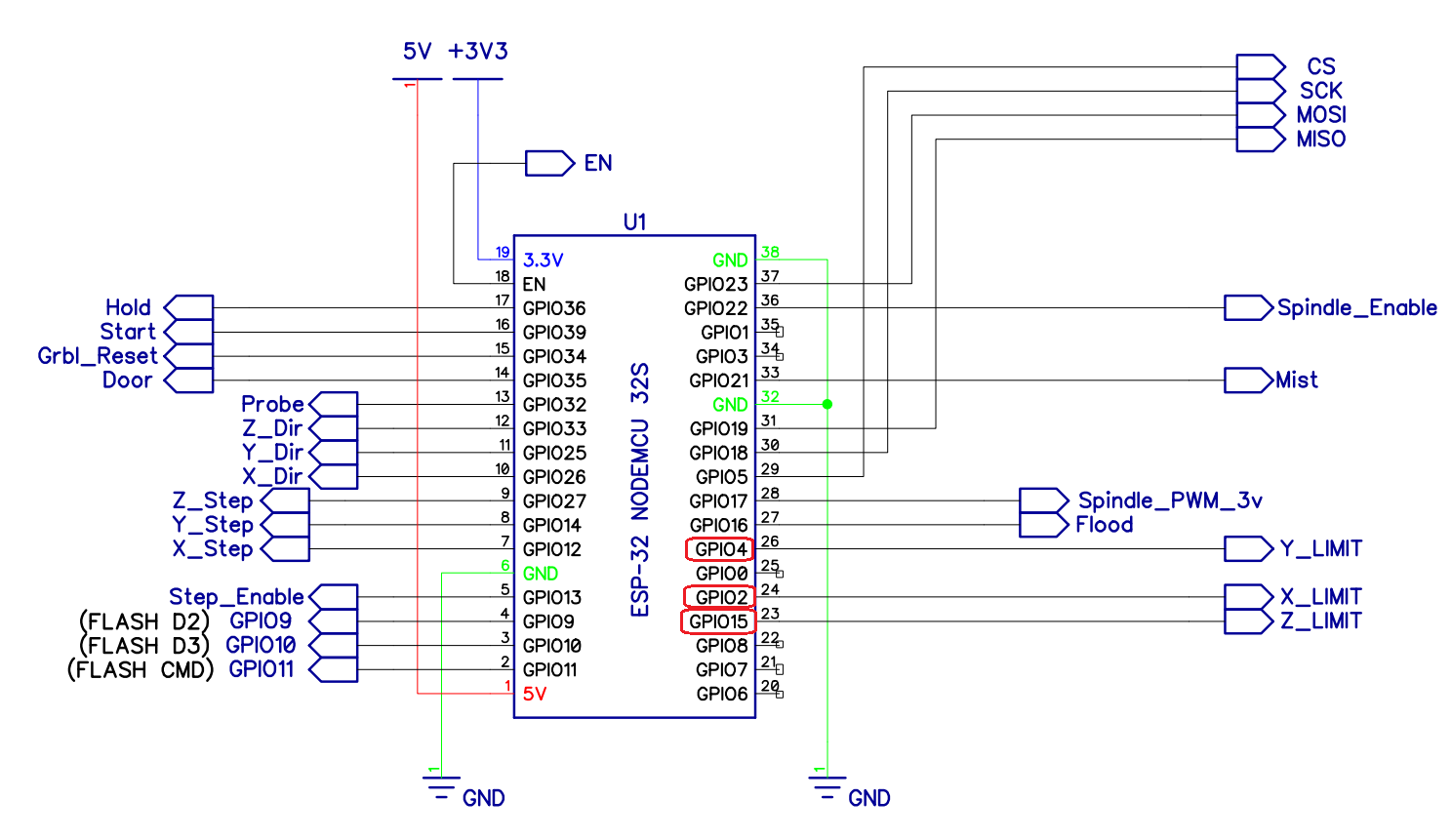
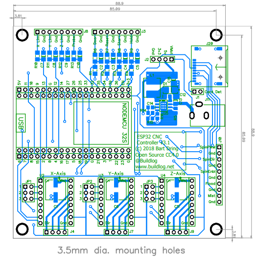
好的,我想我在 pdf 中找到了它们。人们是否有更容易找到引脚映射的途径?感谢您在这里的工作! 因此,您似乎使用了 RC 过滤器。你会推荐什么价值观?开关上的NO或NC? 我还需要做些什么才能使其正常工作吗?
|
|
只需在 CPU 映射中查找或更改它们: |
|
cpu图就是这个 #ifdef CPU_MAP_ESP32
// This is the CPU Map for the ESP32 Development Controller
// https://github.com/bdring/Grbl_ESP32_Development_Controller
// https://www.tindie.com/products/33366583/grbl_esp32-cnc-development-board-v35/
...
我建议使用 V4 版本。 还有限位开关去抖动可以帮助消除噪音。 |
|
为什么选择 V4?我有 V3 工作,有什么区别?谢谢。 |
|
一些 i/o 在 V4 上被改组了。主要原因是 io2。大多数开发板在 io2 上都有一个 LED,如果将其用作输入,可能会出现问题。由于某种原因,我从来没有遇到过这个问题,但是很多人都报告了它。它必须接近阈值。 io2 用于 V3 及更早版本的 x 限位开关。在 V4 上,它是主轴 PWM。它可以很好地用作 PWM 输出,因为您可以看到亮度变化。其他一些东西也在左右移动。 我所知道的关于 ESP32 gpio 的一切都在这个 wiki 页面上。每次我学到新东西时,我都会添加它。 |
|
当 esp32 开发套件在 EN 引脚上有复位时,为什么复位与 P34 相关联。 |
|
这是一种不同类型的重置。grbl 重置是一种“软”重置 grbl 的方法。
通常,软复位会清除 Grbl 的缓冲区,但您不会松动位置,也不需要重新归位。 你不需要按钮。软重置也可以通过 Gcode 发送器完成。 附上你的 cpu_map |
|
请将您的地图粘贴到回复中。 …只是您正在使用的那个。 |
#ifdef CPU_MAP_ESP32_LPCNC
  // This is the CPU Map for the LPCNC Shield

  // It is OK to comment out any step and direction pins. This
    // won't affect operation except that there will be no output
    // form the pins. Grbl will virtually move the axis. This could
    // be handy if you are using a servo, etc. for another axis.
    #define CPU_MAP_NAME "CPU_MAP_ESP32_LPCNC"

    #define X_STEP_PIN        GPIO_NUM_12
    #define X_DIRECTION_PIN   GPIO_NUM_14
    #define X_RMT_CHANNEL   0

    #define Y_STEP_PIN        GPIO_NUM_27
    #define Y_DIRECTION_PIN     GPIO_NUM_26
    #define Y_RMT_CHANNEL   1

    #define Z_STEP_PIN        GPIO_NUM_25
    #define Z_DIRECTION_PIN     GPIO_NUM_33
    #define Z_RMT_CHANNEL   2

    // OK to comment out to use pin for other features
    #define STEPPERS_DISABLE_PIN GPIO_NUM_13

    // *** the flood coolant feature code is activated by defining this pins
    // *** Comment it out to use the pin for other features
    // #define COOLANT_FLOOD_PIN   GPIO_NUM_16
    //#define COOLANT_MIST_PIN    GPIO_NUM_21

    // If SPINDLE_PWM_PIN is commented out, this frees up the pin, but Grbl will still
    // use a virtual spindle. Do not comment out the other parameters for the spindle.
    #define SPINDLE_PWM_PIN    GPIO_NUM_17
    #define SPINDLE_PWM_CHANNEL 0
    // PWM Generator is based on 80,000,000 Hz counter
    // Therefor the freq determines the resolution
    // 80,000,000 / freq = max resolution
    // For 5000 that is 80,000,000 / 5000 = 16000
    // round down to nearest bit count for SPINDLE_PWM_MAX_VALUE = 13bits (8192)
    #define SPINDLE_PWM_BASE_FREQ 5333 // Hz
    #define SPINDLE_PWM_BIT_PRECISION 8   // be sure to match this with SPINDLE_PWM_MAX_VALUE
    #define SPINDLE_PWM_OFF_VALUE     0
    #define SPINDLE_PWM_MAX_VALUE     255 // (2^SPINDLE_PWM_BIT_PRECISION)

    #ifndef SPINDLE_PWM_MIN_VALUE
        #define SPINDLE_PWM_MIN_VALUE   1   // Must be greater than zero.
    #endif

    // #define SPINDLE_ENABLE_PIN  GPIO_NUM_22

    #define SPINDLE_PWM_RANGE         (SPINDLE_PWM_MAX_VALUE-SPINDLE_PWM_MIN_VALUE)

    // if these spindle function pins are defined, they will be activated in the code
    // comment them out to use the pins for other functions
    //#define SPINDLE_ENABLE_PIN  GPIO_NUM_16
    //#define SPINDLE_DIR_PIN   GPIO_NUM_16

    #define X_LIMIT_PIN       GPIO_NUM_34
    #define Y_LIMIT_PIN       GPIO_NUM_35
    #define Z_LIMIT_PIN       GPIO_NUM_32
    #define LIMIT_MASK        B111

    // if using a probe, Door, Reset, Hold, Start, Servo or Solenoid uncomment and asign a pin
    // Useable pins are 0,15, 21, 22, 32, 34, 35, 36, 39
    // Pins 34, 35, 36 and 39 need external pullup
    //#define PROBE_PIN             GPIO_NUM_32
    //#define CONTROL_SAFETY_DOOR_PIN   GPIO_NUM_35
    //#define CONTROL_RESET_PIN         GPIO_NUM_34
    //#define CONTROL_FEED_HOLD_PIN     GPIO_NUM_36
    //#define CONTROL_CYCLE_START_PIN   GPIO_NUM_39

    //#define USING_SERVO  // uncomment to use this feature
    //#define USING_SOLENOID // uncomment to use this feature

    #ifdef USING_SERVO
      #define USE_SERVO_AXES
      #define SERVO_Z_PIN   GPIO_NUM_27
      #define SERVO_Z_CHANNEL_NUM 3
      #define SERVO_Z_RANGE_MIN 0
      #define SERVO_Z_RANGE_MAX 10
    #endif

    #ifdef USING_SOLENOID
      #define USE_PEN_SOLENOID
      #define SOLENOID_PEN_PIN GPIO_NUM_16
      #define SOLENOID_CHANNEL_NUM 6
    #endif


#endif
这个 cpu_map 条目用于我的 diy 板 |
|
您遇到的具体问题是什么?我刚刚将您的 cpu 映射加载到 ESP32 开发套件上,并且 x 限制工作正常。 这是从我的串行监视器中截取的。这显示了来自 ? 命令。我将针脚 34 接地,看到针脚 X 并将其连接到 3.3v,但看不到 X。这是一块没有上拉电阻的松散电路板,因此断开连接时,X 和 Y 可以是任何东西。 没有重置。 |
|
当您添加上拉并触发它重置的限位开关时,无需上拉即可正常工作。 |
|
上拉不应影响任何事情。你拉到3.3V吗? 固件中没有硬编码引脚。这一切都参考了cpu映射。 限位开关操作在 system.cpp 中定义。它们附加到读取它们的中断。System.cpp 从 cpu 映射中获取所有 GPIO_NUM。 |
|
您是否在串行控制台中看到类似[MSG:Reset via control pin]的文本? |
|
是的,拉 3.3V 刚刚检查它是否疼痛。 rst:0x1 (POWERON_RESET),boot:0x13 (SPI_FAST_FLASH_BOOT) [MSG:轴数 3] [MSG:Client Started] grbl 1.1f [‘$’求救] |
|
那是硬重置(POWERON_RESET)。Grbl 重置没有这样做。 Grbl reset via button 会将此文本发送到串口[MSG:Reset via control pin]。您将看不到该启动文本。 这也不是固件崩溃或看门狗超时。崩溃时,您将看到一些回溯信息。 通过单击连接到 EN 引脚的 ESP32 重置按钮,我得到了你所得到的。 |
|
哇,我弄错了。 |
|
好的,很好。 串行控制台总是会提供很多线索。 |


杰西特尔 评论 on 26 Oct 2019
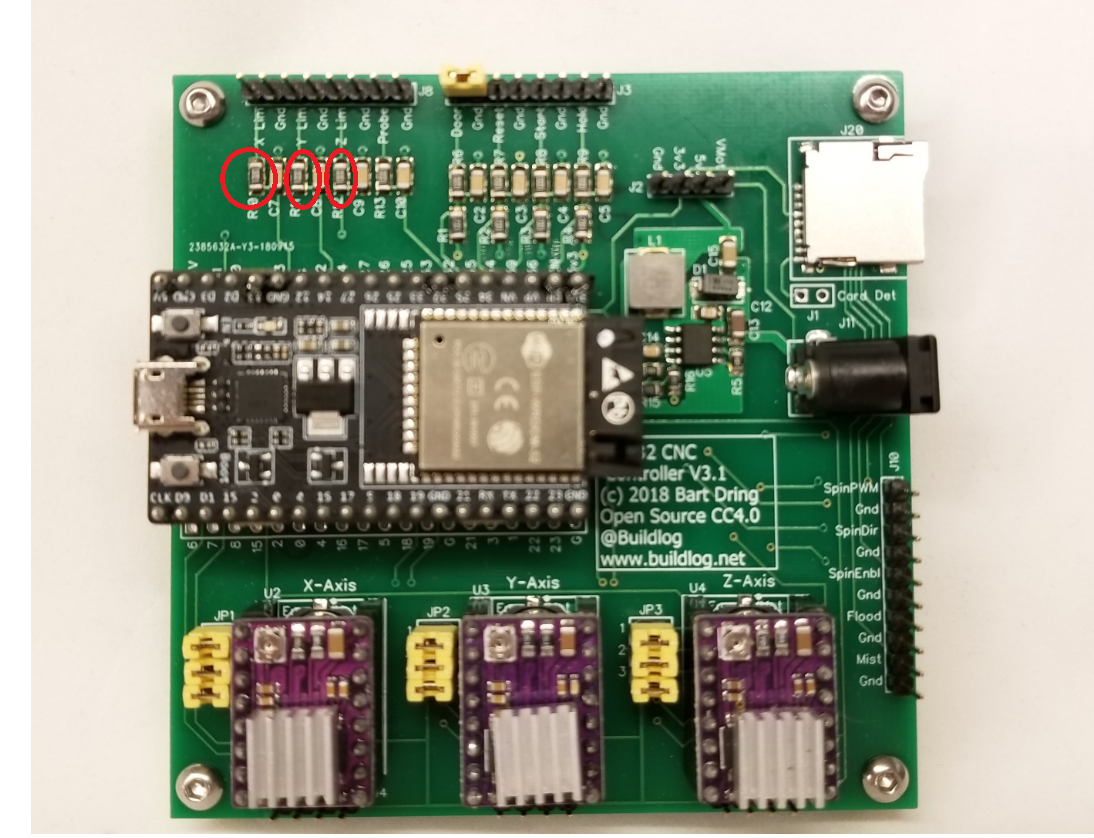
很抱歉将此作为问题发布,我在所有错误的地方寻找,但限位开关的引脚在哪里?你建议用什么电路来帮助消除噪音?看起来这里有一些电阻。

它们还具有 R/C 滤波器,以消除因错误触发开关而产生的高频噪声。
整个引脚映射在哪里?
我浏览了以下内容:
https://github.com/bdring/Grbl_Esp32/wiki/Setting-Up-the-IO-Pins
https://github.com/bdring/Grbl_Esp32/blob/master/Grbl_Esp32/grbl_limits.cpp
https://github.com/bdring/Grbl_Esp32/blob/master/Grbl_Esp32/grbl_limits.h
https://github.com/bdring/Grbl_Esp32
https://github.com/bdring/Grbl_Esp32/wiki/Controlling-Grbl_ESP32
http ://www.buildlog.net/blog/wp-content/uploads/2018/10/outline_esp32_cnc_test_v3p1.pdf